How to Optimise Your Prototyping Process
Prototype Testing – What and Why?
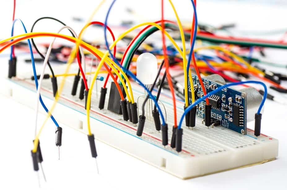
When designing a new printed circuit board (PCB), there are several things we can do to produce a useful first-time prototype and allow for easier debugging. A typical approach often looks like this:
- design calculation
- simulations
- hands-on work with stripboards and reference boards from component manufacturers
- schematic design
- PCB design of the first board
This first prototype is likely to be the most expensive and – arguably – the most important board that an engineer will do on a project. The purpose of the prototype is to prove requirements have been met, check the feasibility of unknowns and give the design team their first working piece of hardware to get something that behaves like the final product to work with.
Designing the first prototype of a PCB is also the most difficult part. Much effort is spent creating the schematics, simulating, reviewing, calculating. Avoiding expensive PCB coasters and time lost to re-spins is incredibly important. Otherwise, these could cost your customer a launch window or lose you those vital first-time customers.
Here are some practical tips to help you limit the risk of creating non-recoverable issues on the first prototype, by designing for prototype testing:
1. Debug Headers
Especially useful for programmable parts in a prototype, missing debug headers give the software development team a bunch of headaches. Having some simple 2.54mm or 1.27mm pitch headers on serial buses are a great help to software engineers debugging serially connected devices.
It’s also beneficial to dedicate some 2 pin headers to GND only; this allows for easy use of croc clips for probing. Tying some spare I/Os to a header for an FPGA can allow easy attachment of a logic analyser – giving another useful debug tool without having to touch a soldering iron.
2. Test points
Always have some test points in your prototype to allow easy measurement of all supply voltages and references. It’s helpful to have something you can clip a probe onto, so that dynamic measurements can be taken; leaving your hands free for scope controls or working a program.
Have test points on spare I/Os of micros or FPGAs too. These extra I/Os come in handy if there is something missing and you just need another output or input. For example, recently, an error caused a critical interrupt line to be missed off the board. Having I/Os free, especially with BGAs, helped cure the issue with a simple mod wire.
Always take the size of the test points and their position into consideration. If it’s a high-speed track or critical clock you want to probe, minimize stub tracks to the test point; that way, you won’t affect the integrity of the signal you are trying to measure.
For assembly of several boards, reduce the time chasing issues through several boards by having TPs/headers for buses accessible at different stages of the assembly. This will help with debug and development later.
3. Ground Connections for Probing
Having plenty of signal test points in a prototype is all well and good, but consideration has to be given to the return path of the probe. Without close GND probing points to complement the test points, you see an increase in ground impedance and ground loop size as you have to connect the ground of the probe to somewhere far away relative to the test point. Large GND loops act as antennas and will pick up a lot of noise from the environment, harming sensitive small signal measurements. Make sure you place convenient clip test points for GND – especially near areas where you need to carefully measure overshoot and undershoot, such as power supplies and high speed circuitry.
4. LEDs
Having some debug LEDs on spare I/O pins can certainly help debug issues – for example, boot loaders sticking before you have managed to bring up a serial port. They can give you quick checks of internal FPGA signals and registers. LEDs attached to power rails provide a fast indication that all the power supply circuitry is operational; saving you precious time hunting for a problem if a rail has been damaged during the development. LEDs are a great visual debug aid in a prototype, enabling speedy checks without any equipment.
5. …Tips 5-12…
Want the rest of our tips covering component boot strapping, multi-part components and more?
Want to optimise your prototype testing process?
Download our eBook “Design for Prototype Testing – 12 Tips for Easier Debugging” – which includes images and diagrams to help you limit the risk of creating non-recoverable issues on your initial prototype.
Download Now >> Design for Prototype Testing – 12 Tips for Easier Debugging
How can ByteSnap help you today?
From start-ups to blue chips, ByteSnap’s embedded systems software developers & electronic design engineers are enabling companies to stay a step ahead by providing them with bespoke solutions. Maintain your competitive edge – contact us today and let your business be among them!