What You’ll Learn
- Systematic inspection techniques to identify common PCB issues before powering up, preventing costly damage to components
- Safe power-up procedures using bench supplies and thermal monitoring to detect problems early in the testing process
- Programming and debugging strategies for integrated circuits, including voltage level matching and timing requirements
- Fault isolation methods to track down short circuits, component failures, and design issues using proper diagnostic tools
- Prevention strategies through design for manufacturability (DFM) practices that reduce the likelihood of future circuit board problems
Spotting and Solving Problems: Circuit Board Bring-up Issues
Design engineers are all too familiar with the nervous excitement of powering up a newly manufactured PCB design for the first time. There is a lot to go wrong during the design and manufacture of such complex systems, and delays in finding problems can significantly impact the time to market for your product.
So, whether it be after that first turn-on of the power supply or after significant software development effort, it’s very likely that a circuit board issue will need to be resolved.
This guide aims to help design engineers track down and fix any unexpected problems with their circuit board.
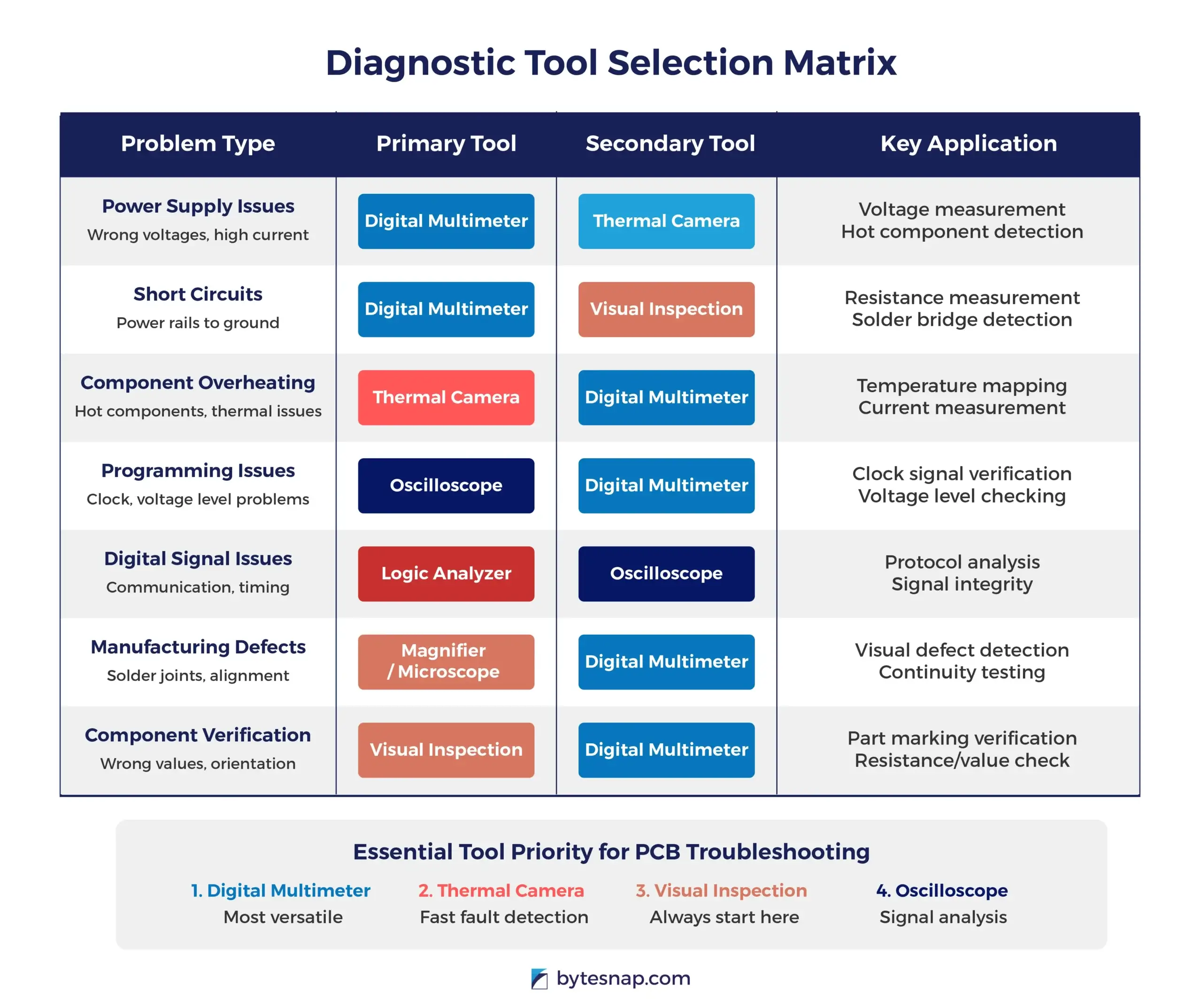
Inspection tools
- PCB inspection jig or magnifier
- Digital Multimeter
- Logic analyzer (Hardware dependent)
- Thermal camera
Rework tools
- At least one soldering iron with temperature control and multiple tips
- Low-temperature solder, flux paste and solder wick
- Hot air rework station
Step-by-Step Inspection
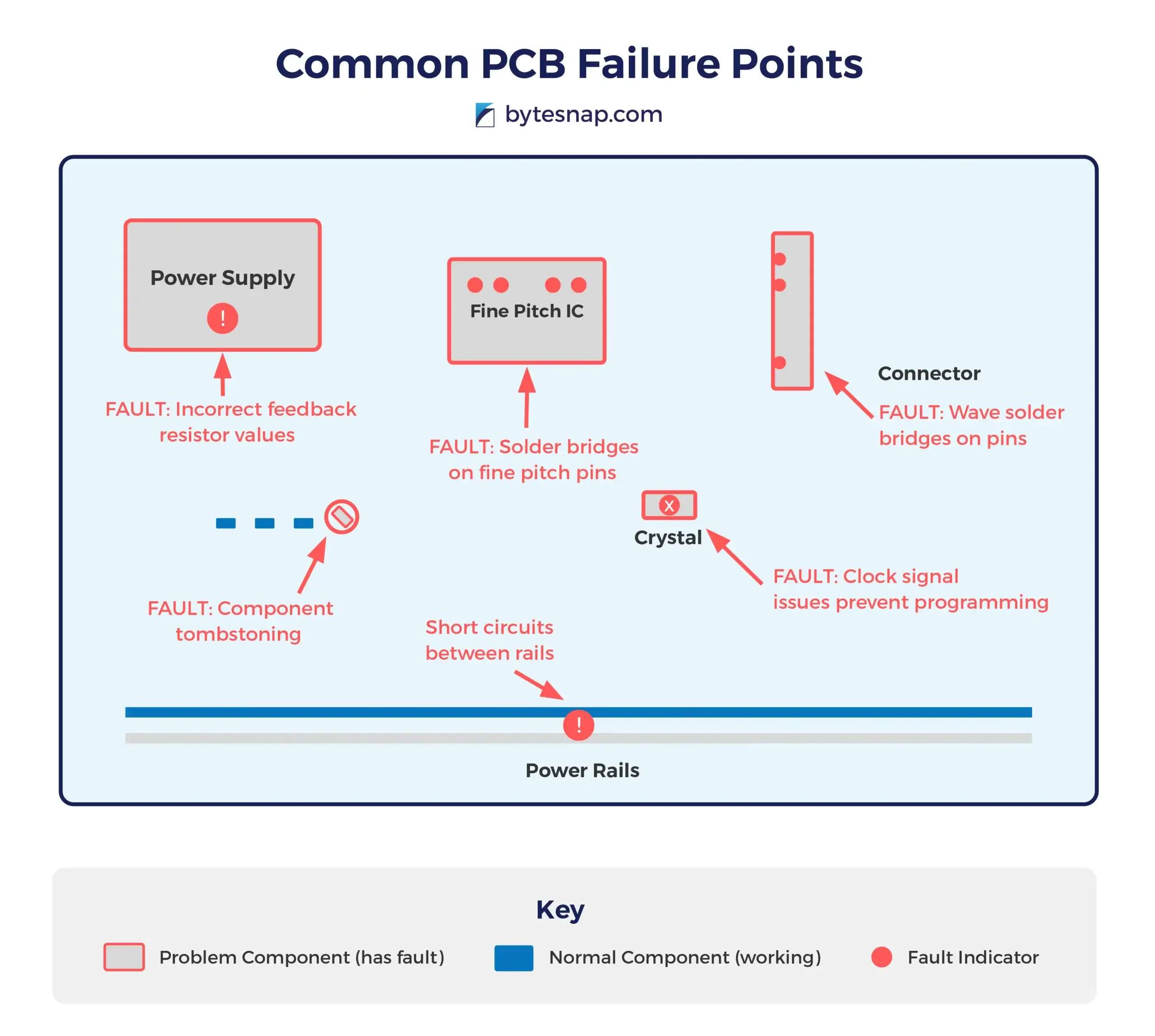
A systematic approach to inspection can save time and prevent damage when power is applied to the PCB for the first time. Begin with a visual inspection, looking for obvious signs of dry solder joints, solder bridging, misaligned surface mount components, and defects or damage to the copper traces or planes.
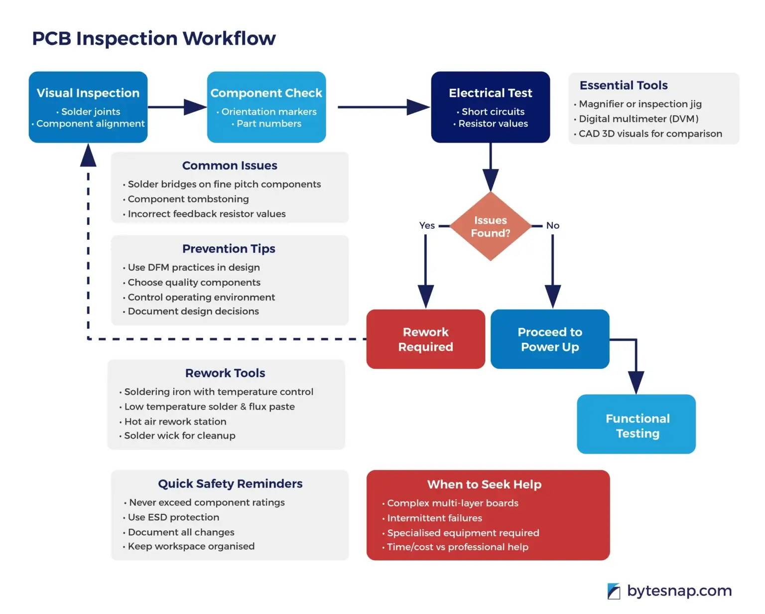
The risk of finding these types of issues depends greatly on the manufacturing process that has been used; for example, solder bridges on connectors and IC pins are more common on PCBs that are wave soldered. If the PCB has been through a reflow oven, then more common issues are component misalignment and tombstoning.
Generally, most manufacturing processes will pick up these issues and the boards will be reworked. It is also worth thoroughly checking parts with unusual footprints or fine pitch, as these can be unfamiliar to assembly houses and defects might not be spotted.
If the design was created in a CAD package with 3D visuals and BOM variants, use this to compare to the physical PCB in front of you.
Look for the orientation markers on parts like ICs and check they align with the marker on the PCB silkscreen; at the same time, you can also check the part number markings are correct.
It will be harder to spot issues with incorrect values on passive parts such as SMT capacitors, inductors, and resistors, especially in small package sizes (0402 and below).
If there are adjustable output DC regulators on the board, they will likely to be set by a resistor divider to a feedback pin. If the values cannot be read off the top of the parts, use a DVM to measure these feedback resistor values to confirm they are correct. Failure to do so before powering up the PCB can risk damage to many other parts on the circuit board.
Using a DVM to check for short circuits between each power rail and ground, is another quick test that can save a lot of rework time.
Initial Power up
For PCBs with DC input, use a bench supply to apply the appropriate voltage and current to your PCB under test. Set the voltage to the nominal level required.
The current limit should be set to give comfortable headroom for initial power-up but low enough to limit damage if a board fault has been missed during the inspection stage.
If your board has a mains AC input and isn’t fused on the board itself, add one externally to limit the power that can be delivered.
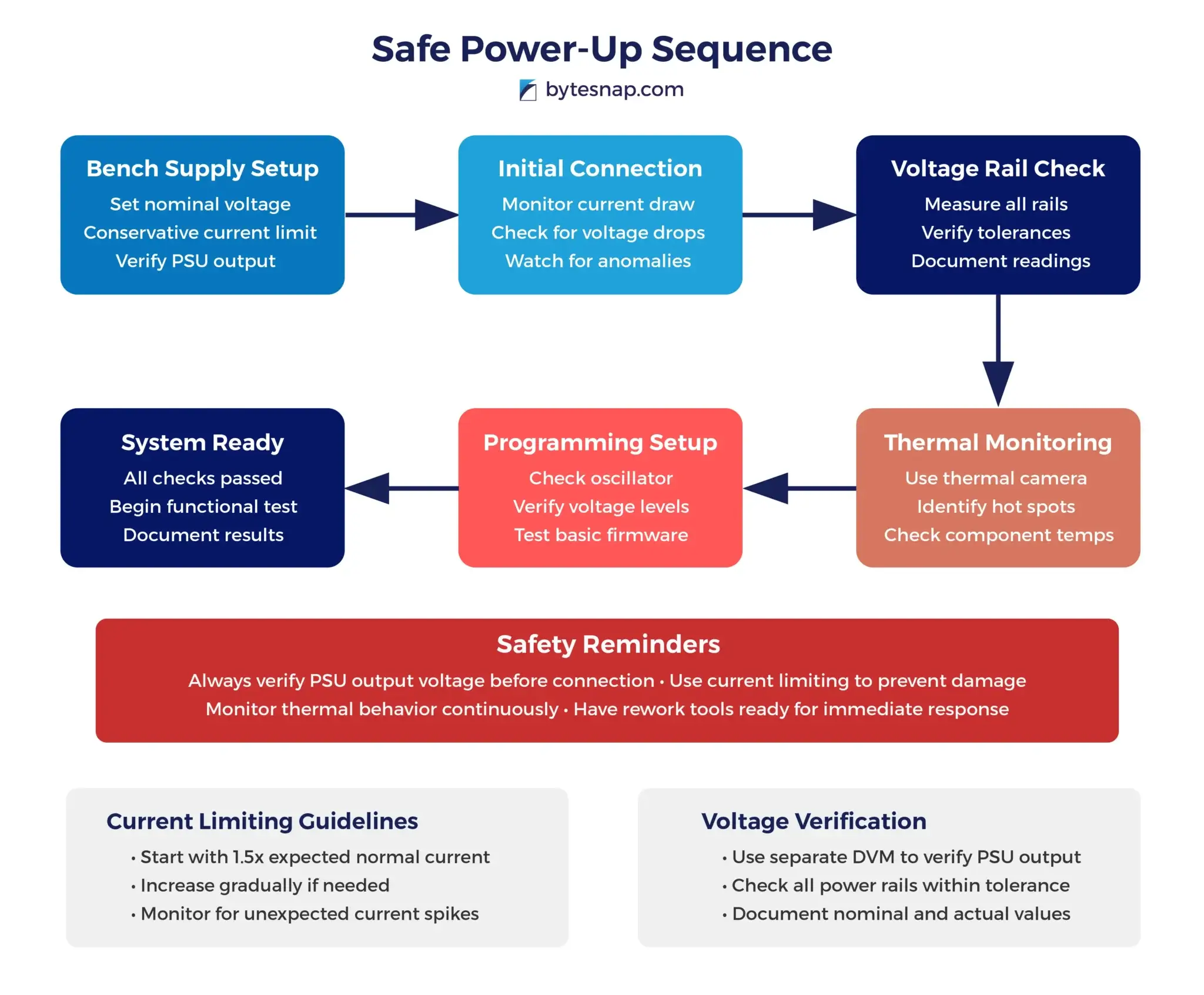
Before connecting up the PCB, use a voltmeter to ensure the output voltage matches the setting on the PSU display – they can be faulty, and this is a very frustrating way to cause damage.
Sometimes parts draw more current than expected on first power-up, and the supply limit may need to be adjusted. It is worth double-checking the power requirements before assuming there is an issue and jumping into debugging the circuit.
If there are no immediate causes for concern, such as the supply voltage dropping close to zero, the voltage rails should be measured with a DVM to ensure they are within their expected tolerance.
At this point, it is also a good idea to monitor the PCB with a thermal camera to help spot any components that are generating more heat than expected. Hot components may be a sign that there is a design or manufacturing issue in a part of the circuit not directly linked to the power supplies. Knowledge of the design or access to the schematics will be crucial in locating the fault.
To advance past basic testing, it may be necessary for integrated circuits to be programmed. To aid the hardware testing, software engineers may be able to provide a basic programming file with all device pins set to default states.
Fault finding after power-up
Sometimes, the source of a PCB fault is very obvious, such as damage like burnt components or swollen capacitors. In other cases, you may need to isolate circuit sections on the PCB to locate the faulty part.
You may find a power supply rail measures close to 0 ohms (short circuit); this can be caused by damage to a number of parts; Multi-Layer Ceramic Capacitors (MLCCs) and MOSFETs tend to fail as a short circuit to ground.
Programming
The first part to check is the external oscillator of the IC to program. If using a crystal, use a low capacitance probe to check the clock signal is at the appropriate voltage and frequency. For crystal oscillators, any probe should be sufficient. Some devices use internal oscillators but may have a “clock out” pin that can be used to check the device is running as expected.
A common error with programming is a mismatch in working voltage levels between the programmer and the target device. Ensure the device and programmer datasheet requirements have been met.
Some devices have very specific timing requirements for voltage supplies; both the turn-on time and sequence specifications should be observed. This is particularly true of devices with many voltage banks. Failure to follow these requirements can leave the devices in an unknown state, in which they may not behave as expected.
Sometimes devices are accidentally held in reset during programming. This may be because the reset line is connected to an onboard controller or other hardware that affects the ability of the programmer to toggle the reset pin as required.
Even when programming software claims to have flashed the target successfully, there may have been undetected errors. It is useful to start with a basic firmware file to flash a GPIO or LED at a defined frequency.
Preventing Circuit Board Problems
It’s better to stop problems before they start. Good circuit board design is key. Choosing quality parts helps too. Controlling the environment where boards are used can prevent damage. Regular checks can catch issues early.
Implementing proper design for manufacturability (DFM) practices can significantly reduce the likelihood of problems during production and in the field. This includes considerations like adequate spacing between components, proper thermal management, and robust power distribution. Also, incorporating built-in test features and diagnostic capabilities can make future troubleshooting much easier.
ByteSnap works in various fields, including the energy sector, where reliable circuit boards are essential. Our experience designing for harsh environments is invaluable in creating robust, long-lasting circuit boards for critical applications.
Real-World Problem Solving
Let’s look at how ByteSnap solved a tough circuit board problem.
A client came with a board that kept failing in hot conditions. ByteSnap’s team checked the board design and found that some parts were placed too close together, causing overheating. ByteSnap redesigned the board layout, spacing out the hot components and adding better cooling. After these changes, the board worked perfectly, even in high temperatures.
In another case, ByteSnap dealt with a circuit board experiencing intermittent failures due to electromagnetic interference. We conducted thorough EMC testing to identify the source of the interference and implemented shielding techniques and filter circuits to mitigate the issue.
This not only solved the immediate problem but also improved the overall reliability of the product.
See Client Success Stories

Wrapping Up: Mastering Circuit Board Troubleshooting
As we’ve explored here, dealing with circuit board issues requires a combination of knowledge, skill, and the right approach.
While the complexities of modern electronics can make troubleshooting a daunting task, following a systematic process can lead to successful problem resolution in most cases.
Let’s recap the key points and strategies for effective circuit board troubleshooting:
- Visual Inspection: Always start with a thorough visual examination. Many issues, such as damaged components, broken traces, or signs of overheating, can be identified through careful observation. Use magnification tools when necessary to spot subtle problems.
- Proper Tools and Equipment: Invest in and use appropriate diagnostic tools. Multimeters, oscilloscopes, thermal cameras, and logic analyzers are invaluable for pinpointing electrical and thermal issues. Ensure you’re familiar with the proper use of these tools to avoid misdiagnosis.
- Systematic Approach: Follow a step-by-step troubleshooting process. Start with the simplest possible causes and progressively move to more complex scenarios. Document your findings at each step to maintain a clear picture of the problem and your progress.
- Understanding Common Issues: Familiarise yourself with frequent circuit board problems like power supply failures, component degradation, solder joint issues, and environmental damage. This knowledge will help you identify potential causes more quickly.
- Preventive Measures: Remember that prevention is often better than cure. Implement good design practices, use quality components, and consider environmental factors to reduce the likelihood of future problems.
While many circuit board issues can be resolved through these methods, it’s important to recognise when a problem exceeds your capabilities or resources.
Complex multi-layer boards, intermittent issues, or problems requiring specialised equipment may necessitate expert assistance. In such cases, don’t hesitate to seek professional help.
This is where services like those offered by ByteSnap become invaluable.
Our electronic design services provide a comprehensive solution for challenging circuit board issues. ByteSnap’s team brings a wealth of experience and a multidisciplinary approach to problem-solving:
- Expert Diagnostics: Using advanced tools and techniques to identify even the most elusive issues.
- Custom Solutions: Developing tailored fixes for unique problems, including redesigns when necessary.
- Holistic Approach: Addressing both hardware and software aspects to ensure comprehensive problem resolution.
- Design Optimisation: Improving existing designs to enhance performance, reliability, and manufacturability.
- Regulatory Compliance: Ensuring that repairs and redesigns meet all necessary industry standards and regulations.
Whether you’re dealing with a malfunctioning prototype, seeking to improve an existing product, or developing a new electronic device from scratch, ByteSnap’s expertise can be a game-changer.
Our ability to seamlessly integrate hardware and software solutions ensures that your circuit board issues are not just fixed, but that your entire electronic system is optimised for peak performance and longevity.
While circuit board troubleshooting can be challenging, a methodical approach combined with the right knowledge and tools can overcome most issues. For those problems that prove particularly stubborn or complex, remember that experienced electronic design consultants like ByteSnap Design are available to provide the advanced support needed to keep your electronic projects on track.
By mastering these troubleshooting techniques and knowing when to call in the experts, you’ll be well-equipped to tackle any circuit board challenge that comes your way, ensuring the reliability and success of your electronic designs.
Expert PCB Design Support - Here When You Need It
Book a discovery call to see how our skilled, flexible hardware engineers can slot in easily alongside your in house .
teams to de-risk, troubleshoot and help you complete your PCB complex designs.
Circuit Board Bring Up Issues - FAQs
Q: What's the most important step before powering up a new PCB for the first time?
Always perform a thorough visual inspection and use a DVM to check for short circuits between power rails and ground. This simple step can prevent damage to multiple components.
Q: How do I know if my current limit setting on the bench supply is appropriate?
Set the current limit to provide comfortable headroom for normal operation, but low enough to prevent damage.
Start conservatively; you can always increase it if the board draws more current than expected during normal operation.
Q: My programming software says it was successful, but the device isn't working. What should I check?
Verify the external oscillator is running at the correct frequency, check that voltage levels match between programmer and target device, and ensure the reset line isn’t being held by other hardware. Try programming a simple LED blink firmware to confirm basic functionality.
Q: When should I consider getting professional help with a circuit board problem?
Seek expert assistance for:
- complex multi-layer boards
- intermittent issues that are difficult to reproduce
- problems requiring specialised equipment you don’t have access to
- or when the cost of continued troubleshooting exceeds the value of professional diagnosis
Q: What's the best way to prevent circuit board problems in future designs?
Implement proper design for manufacturability (DFM) practices including adequate component spacing, robust power distribution, proper thermal management, and built-in test features. Choose quality components and consider the operating environment during the design phase.

Founded in 2008, ByteSnap Design is an award-winning embedded systems design consultancy, offering a comprehensive range of services across the electronic product development lifecycle.
A highly skilled team of over 40 hardware and software engineers, our expertise spans several sectors, including IoT, automotive, industrial, medical, and consumer electronics.
The engineering consultants on the ByteSnap Editorial Team share their knowledge and practical tips to help you streamline your product development and accelerate designs to market successfully.
With their deep technical expertise and practical experience, they aim to provide valuable insights and actionable tips to guide you through the complex world of electronic product design and development, to help you bring innovative, reliable, and secure electronic products to market quickly and cost-effectively.