Here’s Why You Can’t Use Raspberry Pi For Your Project
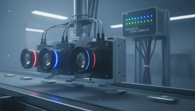
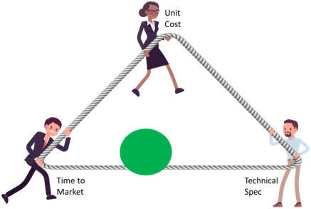
Have you ever worked on a project that started out like this?

And ended up looking like this?

The initial impression of a clear-cut solution that could be delivered on time and under budget has been washed away.
Unfortunately, misconceptions around different technology and a lack of realistic planning cause this to occur fairly often.
It is for good reason that consultancies such as ByteSnap have a Design Rescue Service to pull projects out of the hole that has been dug for them.
The intention of this article is to challenge a very common misconception and illustrate the problems and difficulties with using a Raspberry Pi or similar maker boards, for an embedded product. I’ll be using a fictional example throughout the article to add clarity to the points being made.
List of contents – coming up:
- An unexpected inquiry
- What is the Raspberry Pi?
- Choosing the best tech
- Technical spec
- Time-to-market
- Planning time-to-market
- Development Cost
- Risk
- Unit Cost
- …Where is Mr. Smith?
- Will I be able to use Raspberry Pi, then? Ever..?
An Unexpected Inquiry
To begin, let’s establish the setting of the scenario:
It is a Monday morning and a telephone call comes through from a potential customer.
The caller introduces themselves as Mr. Smith from Simon’s Printing Company and explains that they are lacking in internal resources and need to outsource their product development.
They then go on to outline a basic specification; it’s the control board for an industrial bar-code printer. They have years of experience and are migrating from a PIC-based design with a mono-LCD to a more sophisticated design with a colour-LCD, touchscreen, and other features to improve the user experience.
However, Mr. Smith then suggests basing the product around a Raspberry Pi, as one of his software engineers has created a Proof of Concept* using one.
This sets our alarm bells ringing.
*Proof of Concept: evidence, usually deriving from an experiment, to prove that something is feasible.
But what’s the problem with Mr. Smith’s suggestion? Is there something fundamentally wrong with the Raspberry Pi?
No, absolutely not.
The problem is that Mr. Smith has made the end technology decision on dubious grounds before the project has even begun.
Mr. Smith has chosen a design that fits the technology, rather than technology that fits the design.
What is the Raspberry Pi?
The Raspberry Pi was first released in 2012 by the Raspberry Pi Foundation in association with Broadcom. Its target market was the promotion and teaching of computer science in schools and the wider developing world. It is a single-board computer, around the size of a credit card.
It has Ethernet, USB, Wi-Fi, and HDMI outputs as well as a GPIO header allowing peripheral boards to be added. There are various models, typically in the £20-40 range.
An explosion in popularity saw its use in robotics and wider applications, and in response to this, the Foundation has begun a partner program, for design houses that design products using the Raspberry Pi.
As of February 2024, over 61 million Pi’s- including Raspberry Picos – had been sold. [1]
Taking a step back though, the Raspberry Pi is part of a wider group of boards called maker boards. Maker boards, broadly speaking, come in two types: demo boards, designed to sell a silicon product – often ARM Cortex M parts – and secondly, single board computers, which generally run Linux.
It is the latter category that the Pi falls into, and which triggers the scenarios outlined at the beginning of the article.
The key attraction of these single board computers is that they are cheap. They offer low-end PC spec performance at a tiny fraction of the cost and therefore are an almost disposable purchase, perfect for product development and experimentation. And with massive forum support, bugs are easy to fix, resulting in a low-stress and low-budget development process.
Therefore, as Mr. Smith’s software engineer had recognised, maker boards are perfect for quickly developing a proof of concept.
However, Mr. Smith has fallen into a common trap, the cost and ease of development are deceptive, and unfortunately, an easy start does not equal an easy path to market.
Industrialising a design and making it marketable requires careful consideration of the choice of technology. It is important to fully explore all options, and not become biased.
Choosing the best tech
Engineering is a creative process – if you gave the same spec to ten different engineers, you would receive ten different solutions back. This is one of the aspects that makes engineering so interesting and exciting to work in.
Every project has a series of hard and soft requirements and key factors that conflict with each other. An increase in complexity often increases development time and cost, in the same decreasing unit cost requires optimisation that lengthens development time.
These ‘trade-offs’ can be represented visually:
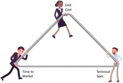
Technical Spec
Put simply, this is what the project needs to do. Every new concept being developed has a purpose and the technical specification is the formalisation of this purpose.
In the context of an electronic product, a technical specification consists of a lot of factors, such as:
● Size
● Power
● Boot time
● Heat
● Form factor
● Certifications
● Temperature range
● Heat dissipation
● I/O
● Wireless interfaces
● Performance
As well as the “hard” tech factors, there are soft requirements, such as reliability and longevity data. Then there are intangible considerations, such as customer perception.
For example, if a customer opens a device up and sees the inside, what will they think?
Time-to-market
This factor also encompasses development time and risk, as these have direct implications on what a reasonable time-to-market can be.
As a result of this, judging how challenging a target time-to-market can only be done in the context of the individual project. When we had a company ask us to create a demo of an AI voice assistant robot for CES in September 2016, we had a fixed time-to-market of 4 months; that was tough. However, when JFK set a 10-year deadline for NASA to put a man on the moon, that was significantly more difficult.
Consequently, the challenge represented by a time-to-market is relative, an easy project with a two-month deadline poses no issue compared to an extremely specific and rigid spec with a year. Additionally, the flexibility of the goal and the economic cost of missing the given target also play a large part in positioning yourself or your customer on the triangle.
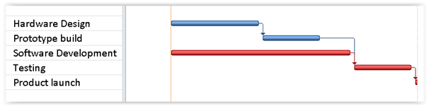
Planning time-to-market
Every project has a best-case scenario, and a Gantt chart representing the time flow of your perfect scenario may look like this:
However, it would be unrealistic to expect the project to run in this way. In fact, the actual time-flow will look more like this:
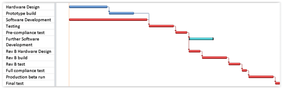
With compliance, extra board-spins, and added software development time, all delaying the product launch and lengthening the overall time-to-market.
Anticipating these delays is sensible and will help manage expectations both of the engineers, and the decision-makers funding the endeavour.
Development Cost
The time-to-market is fundamentally the time taken to develop the project, and therefore a long project will inevitably cost more. In our triangle of compromise, the development cost is coupled with time-to-market, due to the influence the cost has on a developer’s ambitions.
A short time-to-market decreases the amount you have to pay your engineers, whether they are outsourced or in-house and also decreases the length of time you have to wait to start earning revenue.
Development cost is primarily:
(Engineer(s) hourly rate * no. hours spent) + overheads
However, it is important to recognise that this is not the only cost that you will incur when taking your next product to market, further actions may reduce some costs while increasing others.
For example, time-to-market can be sped up by purchasing 3rd party software or increasing the size of the engineering team, yet this will not necessarily decrease development costs.
Finally, any electronic product must conform to state or market standards, and therefore some level of compliance testing will always be required. In some cases, this can cost more than the rest of the development cycle combined, especially if multiple runs are required.
So, the development cost equation is more like this:
(Hourly rate * hours spent) + overheads + 3rd party licenses + certification + …
It is perhaps becoming clearer that time-to-market, in reality, has its own conflicts – a strict deadline can be achieved in multiple ways, and just because the development cycle is shorter or longer, does not necessarily define the development cost.
Risk
The other piece of the time-to-market jigsaw is risk. The creator of the Dilbert comic strip Scott Adams said:
“The risk/reward calculation for engineers looks something like this:
Risk: – Public humiliation and the death of thousands of innocent people.
Reward: – A certificate of appreciation in a handsome plastic frame”
While this is a satirical analysis of risk in engineering, it is not perhaps as ridiculous as it seems. All projects have associated risks at every level; for the engineers, the company, and the final user. Some examples of common risks from a development point-of-view are:
- Risk of not meeting tech spec
- Of obsolescence
- Of failure to deliver
- Of missing the price point
As a generalisation, engineers are risk-averse, however, this can result in over-engineering, impacting both time-to-market and cost (unit cost and development). Using tried and tested practices will usually result in decreased risk, however, this is provided that the elements chosen are a good fit for the design.
Unit Cost
Finally, at the top of our triangle of development conflict, there is unit cost. This is represented in different ways and has many contributing factors, including:
- Base board
- Expansion board
- Enclosure and cables
- Assembly
- Production test cost
- S/W licenses
This becomes more complicated again, as with consumer products the shipped cost is king. However, for industrial equipment, the cost of ownership is more important as the cost of installation, maintenance and failure is much higher. We have now explored the different priorities that help define the best technology for a project, so …
…Where is Mr. Smith?
Mr. Smith has sent us some figures and expects a volume of 1000 pieces per year and a healthy profit margin.
Therefore, this is not a unit cost-driven project.
He has a moderately demanding technical specification and a soft market window launch, but a focus on the development budget. Therefore, on our triangle, his project would be positioned approximately here:
Our prospective customer wants a Linux system and due to the commonality of this request, they have a choice between three options:
- a fully bespoke design
- a single-board computer
- a subassembly such as an SoM
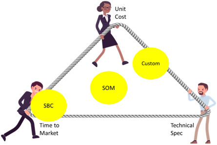
To give some perspective, this is how the three options would look on our triangle approximately:
As is shown, there are advantages to each option depending on your priorities, and therefore there is a clear area where a maker board (shown as SBC for Single Board Computer) such as the Raspberry Pi would be the appropriate option.
The single-board computer is ideal where time-to-market is the number 1 factor, so the lack of flexibility and high unit cost are not a concern. Besides the SBC, a fully custom design allows for the technical specification to be precisely met and the unit cost to be minimized. However, this results in a long time-to-market, higher development costs, and increased risk.
Finally, the sub-assembly approach (SoM) is a halfway house for the two options.
Given that the customer has picked a Raspberry Pi – an SBC – perhaps he is looking for a solution that fits here:
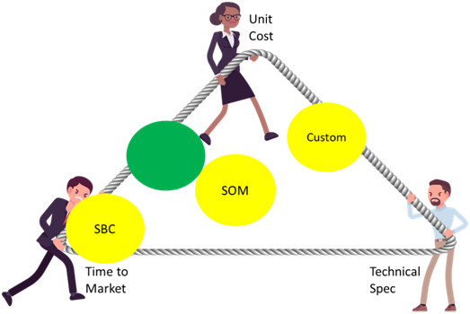
In summary, a product that can be developed quickly, cheaply, and result in a low unit cost. His priorities clearly differ from the restraints of the project.
That said, could this truly be a one-size-fits-all solution?
Will I be able to use Raspberry Pi, then? Ever?
From our perspective, there is a healthy range of Pi’s currently on the market, with the following having both Wi-Fi and Ethernet capabilities:
- Raspberry Pi 3 Model B
- Raspberry Pi 3 Model B+
- Raspberry Pi 4 Model B (all variants: 1GB, 2GB, 4GB, and 8GB RAM)
- Raspberry Pi 5
The Pi 3 Model B+ and all variants of the Pi 4 Model B also have both Bluetooth and >1.2GHz CPUs. Using these boards for an embedded application with a few menu screens operating a slow piece of hardware is equivalent to driving a Mustang in a 20mph zone.
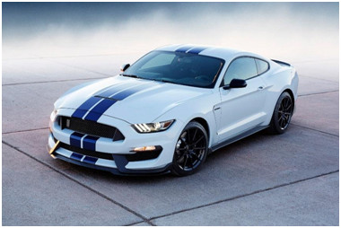
This may be interpreted as ‘playing it safe’; the Raspberry Pi has plenty of power left over for more complex updates and could be upgraded to do more in the future.
However, for most embedded applications the speed is simply not useful. The impressive spec the Raspberry Pi comes with results in large power consumption, much like the Mustang.
That said, Mr. Smith’s product is almost certainly going to be mains powered, and beyond IoT, the power consumption and extra horsepower is completely irrelevant, particularly as the Raspberry Pi has all this extra power for less money.
To back up the Pi3 and 4 for one hour while running requires a battery of approximately 2Ahr, which is almost 3 times what common SoM modules require. High power consumption also causes heat dissipation issues when the CPU is working hard. This actually works to Pi’s advantage, as with its huge power, it is unlikely to ever be worked to the point where it overheats.
However, the temperature range could be an issue for this product – the Raspberry Pi has a commercial operating temperature range of 0-50 degrees Celsius.
In general, this is true across all maker boards and is completely inappropriate for an industrial environment. This seems surprising, yet, returning to what the Raspberry Pi was originally intended for – educating future programmers and engineers, whose bedrooms are unlikely to get close to either end of the 0–50-degree spectrum – maybe it is not a surprise after all.
We go back to Mr. Smith all these facts and he is not concerned about the temperature range, so we investigate the unit cost for 1000 pieces:
● Pi 3B + SD card + HAT connectors = $42
● Motherboard ($40)
o LCD connector
o RTC
o RS485 buffer + logic
o Power supply
o Battery charger
o LCD + touchscreen
o Case + cable assembly
● Total = $154
Software Development
Up until this point, the focus has been on the hardware sections of the project.
However, the way software is developed on the different options is at least an equally large factor when choosing the best technology for a project.
Firstly, developing on a maker board initially is easy and fast – and this is one of their main attractions. There is a plethora of online guides and resources, and in addition, you may find a similar project to your own online that you can bootstrap.
Typically, you will use an SD card image that you can download and configure on the device itself, then resave the image back to the card. This image can then be copied and deployed to other products. When entering the product, you would batch copy the card.
While this sounds very clean and simple:
What happens if you deviate from that stock image?
For instance, you need to alter the bootloader or add drivers to support currently unsupported hardware. This neat solution now could need a new display, RS485 support that involves GPIO changing the transmit direction or power management.
To illustrate, here are some issues encountered with software development on maker boards:
- Binary images
- Stock OS images are consumer-centric
- Lack of revision control
- Boot loader problems
- SD card cloning for distribution
- No access to hardware data
If anything, the problems that arise during software development are worse than the hardware issues, and they add to development cost and time. This increase in time and cost is a contradiction to the initial arguments in favour of these boards.
After all these factors are taken into account, using a maker board such as the Raspberry Pi is now blatantly inappropriate for Mr. Smith’s proposed project. A full custom design is also a poor fit, but if you refer back to our triangle, an SoM looks like a good fit.
Using the Digi CC6UL SoM as an example, this is the spec:
- -40 + 85 C temperature range
- RTC in CC6UL
- WiFi
- Accelerated Compliance testing
- Longevity guarantee
- Tech Support
- Ability to change the mechanical form factor
As well as an improved temperature range and real-time clock, access to source code solves most of our software development issues.
In addition, this solution is only slightly more expensive, with a total BOM cost of $162. As a rule of thumb, SoM modules will have a somewhat pricier material cost, however, as demonstrated this more than makes up for the difficulty associated with the Raspberry Pi for an embedded project like this.
Conclusion
Maker boards are a brilliant concept and an invaluable resource for training the next generation of engineers, as shown by this maker event in Porto Alegre, Brazil:
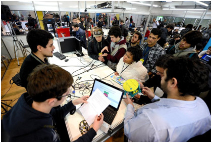
Image credit: fisldezesseis, CC Search – CC BY-SA 2.0
However, the use of maker boards in industrial design and embedded products beyond the prototyping stage requires a lot of compromises and can even be impossible. This is due to the massive inflexibility of the boards that leads to assorted technical issues.
The most important action prior to starting any project is to fully explore your requirements, limits, and all options.
In Mr. Smith’s scenario, an SoM module was the ideal fit; nevertheless, this will not be the case for every project…
Returning to the start of the article, there is nothing wrong with the Raspberry Pi, but the best products always have the technology chosen to fit the design and not the other way around, and just because it is easy to build a proof of concept using a maker board does not mean it can be industrialised using the same technology.
As a final note – the worst maker board fit I’ve ever encountered:
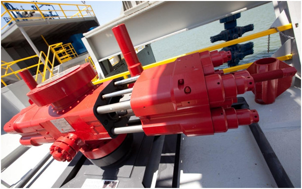
Image credit: eschipul, CC Search – CC BY-SA 2.0
This is an image of a BOP or blow-out protector. It is a huge valve that sits on the sea bed above an oil well, ready to close in case of a blow-out.
In 2011, it was the failure of one of these devices that caused the environmental catastrophe at Deepwater Horizon.
If we positioned this product on our trade-off triangle it would look like this:

Unit cost is completely irrelevant, and reliability and safety are essential.
Despite this, incredibly, two years after the Deepwater Horizon explosion we were contacted by a customer wanting to design a BOP using a maker board…
…needless to say, that the project never went ahead.

Dunstan is a chartered electronics engineer who has been providing embedded systems design, production and consultancy to businesses around the world for over 30 years.
Dunstan graduated from Cambridge University with a degree in electronics engineering in 1992. After working in the industry for several years, he co-founded multi-award-winning electronics engineering consultancy ByteSnap Design in 2008. He then went on to launch international EV charging design consultancy Versinetic during the 2020 global lockdown.
An experienced conference speaker domestically and internationally, Dunstan covers several areas of electronics product development, including IoT, integrated software design and complex project management.
In his spare time, Dunstan enjoys hiking and astronomy.