Saving Power in Low Power Wireless Radio Systems
Introduction
Recent statistics show the number of IoT devices worldwide is expected to reach more than 29 billion by 2030. That’s nearly double the 2020 figure of 15.1 billion. In China alone analysts expect there’ll be 8 billion consumer devices in use. With increasing sales of electric vehicles, and a planned 42,000-home ‘smart city’ being built in Singapore, advances in IoT technology will have never had a bigger impact on day-to-day life.
Connected devices are in use everywhere: from smart thermostats, to smart watches and cloud hosted gaming platforms. The revolution has even spread to normal household items such as fridges and washing machines. Our 2023 industry predictions forecast growing industry support for Matter Standard – the long-awaited boost for IoT expansion and interoperability.
Despite this rapid growth, developing wireless devices remains incredibly challenging. The increased use of connected (IoT) devices, is matched by an ever-growing reliance on small batteries. This pressure to reduce battery dimensions while simultaneously improving the features work at odds with each other, raising development costs and time.
When ByteSnap is approached with a new concept for a Low Power Wireless device, there are invariably two key requirements:
- what the device needs to be able to do – in particular, range of connectivity
- how long the battery needs to last
Additionally, there are other requirements, such as a fixed dimension or BOM (Bill Of Materials) cost that further restrict the project.
For example, a water meter that measures chemicals and quantity that needs to last for ten years, and needs to periodically transmit a report to a monitoring centre.
The balancing act
Reducing power consumption is a device that is one of the most challenging aspects of Low Power design. Yet it is essential, as it is impossible to achieve the desired functionality, and have a battery life measured in months and years, rather than days.
Every successful Low Power Wireless Device currently on the market is a result of a successful balancing act. The developer has considered their priorities and made a series of compromises that have resulted in a happy medium.
These compromises usually involve:
- Time
- Transmission time
- Receiver on time
- Time
- User Interaction
- Transmission / Reception Frequency
- Link budget
- Communications distance
- Speed of communications
- Data size
- Robustness
- Security
- Link budget
- Battery
- Size
- Technology
- Battery
This article is for at anyone interested in, or in the process of, developing a new low power wireless connected product, and aims to provide advice and some key considerations to help you achieve your requirements.
We take an in-depth look at why it’s important to save power in low power radio systems and reveal our top tips to help you achieve this.
The guide will look in detail at three aspects of low power design and how your product can be optimised for battery life: System Choices, Hardware Design and Device Management.
Chapter 1
System Choices
Decisions made at the beginning of a project set in stone what you can achieve. Designing for low power from the outset is what will make your product a star performer.
Type of Radio
The first consideration is the type of radio to use. This depends on several factors such as data rate, amount of data being transferred and required range.
There are different types of low power radio:
- short range like ZigBee, Thread, Bluetooth and Wi-Fi,
- long-range low power radio including LoRa, SigFox and Weightless
- and cellular radio systems.
Wavelength
Some radio wavelengths propagate much better than others – and better propagation means increased power-efficiency. Typically, lower frequencies propagate better than higher frequencies, but the compromise is that the possible data rate is lower.

The RF spectrum is split into various wavebands which are assigned to specific purposes. The majority of the RF spectrum is out of bounds to use without a license, having been assigned to military or commercial broadcasters. However, a number of license free ISM bands are available as long as rules of maximum power and duty cycle are adhered to.
These areas – known as Industrial, Scientific and Medical (ISM) bands – are basically free for general use within certain limitations. The ISM bands available vary from region to region, and some devices are required to communicate over different bands in different regions to adhere to these laws.
2.4 GHz is a worldwide ISM band; this is used for short distance/high data rate communications and is used by Wi-Fi, Bluetooth, ZigBee and Thread to name a few.
Other commonly used bands include 868MHz which is used in Europe typically for longer range but lower rate telemetry such as LoRa. The 433MHz ISM band is European-wide but it is a very common band used by car key fobs, remote controls and other similar devices. As implied, these bands are Europe-specific, other regions have equivalent frequencies, such as 915MHz which is used in the USA.
Higher frequencies tend to cover shorter distances but have higher bandwidth and therefore greater transmission speeds. The longer the distance you need to communicate over, generally, the slower the speed you can use.
With a short distance (10s of metres) network using 2.4GHz, you will achieve around 100 Kbps data rate transmissions. But for long-distance communications (2km or more), using LoRa, for example, a data rate of 50Kbps is an optimistic target – most devices operate at less than this.
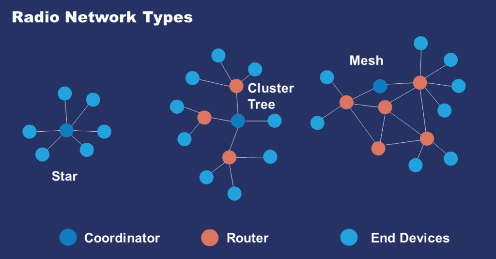
Also, consider the radio system topology; this can increase efficiency and speed of the system when managed correctly.
Star topologies are advantageous when the master device is not battery powered and is able to solely manage the network load.
Alternatively, where all devices are low power, a mesh network with lots of repeaters could be more suitable.
Microcontroller
The choice of microcontroller is normally straightforward and the designer will usually have a family/manufacturer they are familiar with. Most small processors these days – PIC-, AVR-, ARM-based – have low power modes that can be used to reduce the power required during operation, where they turn off clocks, etc., and go to sleep. They rely on an interrupt to wake them up again.
Many of these systems also have a fast wake up system; because if you’re going to go into a deep sleep mode, you need to wake up very quickly to reduce on time to a minimum and thus reduce power used.
Power source
The next consideration to think about is how you’re going to power the device.
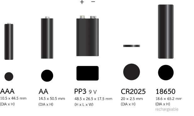
A lot of low power devices are now being powered by batteries. There are a variety of different batteries and technologies and each has different characteristics that affect how well they will work with a particular system and radio.
The breadth of low power wireless means that battery choice varies across every project. However, when the radio system will require infrequent bursts of current, or the battery needs to be rechargeable, battery is often quickly limited.
Reference to the battery manufacturer data sheets will show the typical start and end voltages and type of discharge curve a particular battery has. Some have a constantly decreasing voltage that gently falls until a terminal voltage is reached at which point the voltage drops steeply, e.g., alkaline cells, others have an almost constant voltage until all power is used, e.g., Lithium polymer.
Battery manufacturer data sheets can help – however, they do not tell the whole story when it comes to low power systems like these. Most datasheets will show battery discharge curves based on a constant current drain and usually at a higher current draw, than a low power system will use, so some interpolation must be used to determine what will happen in a low power system.
Also, radio systems like this tend to use very little power whilst sleeping and then require large pulses of current when awake for receiving and transmitting. Some batteries are not suited to this, for example the popular CR2032 lithium coin cell is good for 3V systems and will deliver a low current for a long time but it is not designed to give the larger pulses of current demanded by some radios.
Environmental factors also influence battery choice and their use. A cold environment will affect a battery, reducing its voltage and therefore the useful battery life of the device. High temperatures can also cause some batteries to fail in spectacular ways.
Choosing the battery as a process is consequently iterative, testing a couple of types that fit the specification is often the best way to find the optimum system.
This table lays out a few characteristics of some common battery types:
| Type | Cell Voltage | Energy Density | Typical discharging temperature range (°C) | Standby Lifetime | Rechargeable? | Max Current |
|---|---|---|---|---|---|---|
| Li Ion | 3.6 | High | 0 – 50 | Low | Yes | High |
| Alkaline | 1.5 | High | -18 – 55 | High | No | Medium |
| NiMH | 1.2 | Low | -20 – 65 | Low | Yes | High |
| Li Coin Cell | 3 | Low | -30 – 60 | High | No (usually) | Low |
| LiSoCl2 | 3 | High | -80 – 125 | Very High | No | High |
Once the battery choice has been made, a cut-off point must be determined.
For example, an alkaline battery has a useful end voltage of around 0.9 volts where around 99% of the available power of the battery has been used. So, given that the usual configuration of alkaline batteries for a 3V system is two in series, the minimum voltage is only 1.8V, which is insufficient for some radio modules.
Scenario:
A radio system has been chosen for a smart meter or home device; it has a minimum voltage of 2.4V:
This is a voltage of 1.2V for each cell, which in this case equates to only 60% of the cell capacity. Thus, assuming a cell capacity of 1250mAH, the system can only use 750mAH of the cell capacity.
At this point, there are two approaches that can be taken:
- Maximising the device life using the average power level. This device has an average power level of 0.1mAH, and therefore a battery life of 7500 hours, or roughly 312 days.
- Conversely, maximising power given the customer expectation of the battery life. The customer will be dissatisfied if the battery needs changing more frequently than once per year. Therefore the power level must be restricted to 0.086mAH to achieve this.
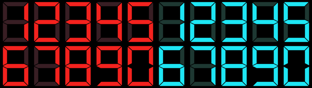
For ultra-low power systems in general, extra caution is required when using components whose performance changes with voltage. LCD displays and LEDs, for example, have batteries that can run down so much that the contrast disappears or the LEDs turn off.
For the best user experience, therefore, you must ensure that the battery voltage you work down to is enough to keep those on.
If the system requires an input voltage that means when a cut-off point is reached whilst the batteries still have worthwhile capacity left (eg if a nominal 3V system cut off at 2.5V), then a boost regulator may be required.
Again, there are compromises to consider in doing this;
- What voltage should the regulator be set to?
- What is the efficiency of the regulator and how does it vary with input voltage?
- What happens when the input voltage is higher than the set voltage, i.e. when new batteries are fitted?
- Does the power wasted by the regulator due to inefficiencies cancel any gains in capacity?
- Could a boost converter fully use the battery’s capacity by draining it to a voltage below which the system would switch off?
Use spreadsheets
Using a spreadsheet can be incredibly useful to determine what compromises should be made to make the design workable and to determine how long a device will last using the selected batteries.
Use a spreadsheet to estimate how much power each part of your design will use. Add the expected battery capacity to estimate how long the battery is going to last. You can be fairly certain you can meet your power targets before you lay out your PCB.
When you have a board, you can measure the actual currents drawn and compare them to the original estimates. The spreadsheet will show more accurately the likely lifetime of the batteries. With competitive timelines, the project literally cannot afford to test to exhaustion, estimation is essential.
For each component enter how much current it takes – when it’s on, when it’s off, how long it’s on for – and using the spreadsheet you can then work out just how much power is being taken and, therefore, how long it will last with the selected batteries.
Initially, the spreadsheet can be filled in using component data sheet values and then updated once measurements are made with a live board.
The spreadsheet can be used to determine how compromises in transmit or receiver timing can affect the battery lifetime.
But to leave it on when asleep only taking around a micro-amp or two may reduce the time by several weeks.
It can also be used to determine how long the transmission should last by determining how much data you need to transmit, and how often that needs to be transmitted. For instance, with a temperature system, how often do you actually need to measure the temperature? If a user is looking at the reported temperature it needs to be fairly often, probably every few seconds. Conversely, a closed system, where the temperature is not displayed, probably doesn’t need to be as often; you could wake up every minute.
A spreadsheet can also be used to determine efficiencies of regulators over the voltage range and current requirements since the regulators generally get less efficient with lower input voltages and/or more current draw from the device.
Use a Watt Hour Meter
Although in the initial design we put these series resistors in so we can measure the amount of current going into a component, that’s fine; except when you’re constantly waking and sleeping, it’s very difficult to determine exactly how much power is being taken by the device as a whole over time.
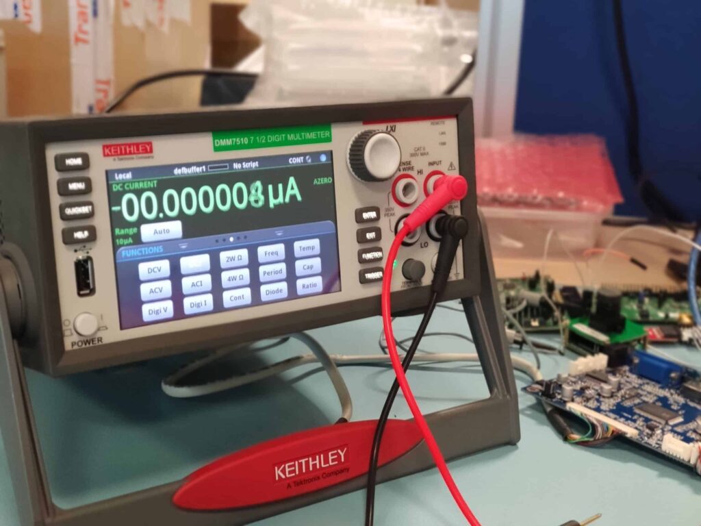
One of the useful things we can do here is to add a Watt Hour meter that monitors the amount of power taken by the device including the pulses you get when the transmit turns on and when it turns off again. To monitor that with a standard meter is difficult because most of the time it’s doing nothing and a meter is too slow to measure the pulse.
If the Watt Hour meter has a low sample rate, it will frequently miss those current pulses. However, over a long period of time, the accuracy will increase – assuming that the pulses are random with respect to the sample rate of the meter – giving you a good average of how much power is being taken by the system.
Bear this sample rate in mind when making your measurements – otherwise you may be fooled by the results!
Chapter 2
Hardware Design
Minimize the pull-ups and other design tips
Low power wireless radio system design requires attention to details that could be ignored in systems where the power consumption is not important.
With normal systems, if they’re mains-powered, you don’t have to worry about elements such as current leakage through pull up resistors. In low power systems, that power consumption can become an issue. For example, if you are looking at a device that takes, 20 micro-amps in sleep mode and then you add a 100k pull up to a 3V rail, then it could take up to 30 micro-amps through the pull-up – that’s doubled your power consumption already.
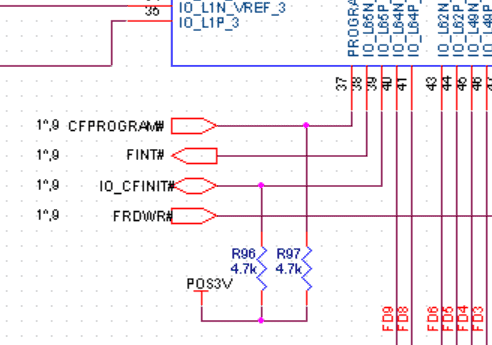
Pull-Up Resistors are shown by the blue jagged line in this CAD image
To avoid that, minimize the number of pull ups etc. that you have on the system and maximise their value.
Add active components such as FETs (Field Effect Transistor) to turn devices and pull up resistors on and off. If you’re measuring temperature every 30 seconds, you can turn that sensor off for 29 seconds out of every 30.
But that can be a bit of a compromise; if the sensor needs setting up, if it has registers that need setting when you turn it on, you will be extending the wake time of the micro. Could the increased power of a longer wake time outweigh the saving from powering down your sensor?
Also, an analogue temperature sensor takes time to settle once power is applied before a true temperature can be determined from it. It could be that for a sensor it has a sufficiently low power state that it uses less power keeping it in that state and reading as required, than the cumulative power of powering it off completely, then reprogramming it each time it is energised. The calculation needs to be made to choose the best solution, with the on-time vs off-time the key factor.
Choose FETs and LEDs carefully
Even though you may only be taking a few milliamps you’ll find that a higher power device that’s rated for a few amps will have a lower VF forward voltage. This means less power is wasted by the FET when it is on.
Part of the design work is to ensure that the components work over the voltage range that you’ve specified. We’ve found devices that – when you look at the data sheet – indicate they will work over the complete range. But upon closer inspection we found that they used internal regulators and worked over three distinct voltage ranges within the total voltage range leaving gaps where they do not operate.
This is fine for fixed voltage designs but with a varying battery voltage led to non-operation at certain battery voltage levels thus requiring a design change to use a different component and a board revision; this is very expensive!
If LEDs are a part of the design, then the colour choice is significant as blue and white LEDs require quite a high voltage. Designs that will operate to a voltage less than around 2.2V cannot use white and blue LEDs as they are likely to stop operating at that point. Using red and green LEDs is a simpler option.
Additionally, you should add to the initial design zero-ohm series resistors into the power rails of all of the active components. Doing this will ensure that once you get that first board, you can replace them with low ohm resistors – of, perhaps, 1 ohm – and measure the voltage across them to determine how much current those components are taking.
Therefore, you can measure the current going into each of the devices and work out which ones are taking more power than expected. Once you’ve done that with the initial design, this will allow you to iron out any other little kinks and get the power down to its minimum.
On the next revision, you can then take the series resistors out of the design.
And remember – user experience and expectations must also be taken into account.
You could design a fantastically low power system which doesn’t satisfy the end user, because they may be expecting it to respond a lot quicker than it actually does.
That’s where some of the compromises come in.
Tune the antenna
Even if range is important in your design, remember to tune your antenna.
By tuning the antenna, you can minimise the transmission power required to achieve your desired range.
Chapter 3
Device Management
Responsiveness and Waking
Where user experience is a factor, the device must reach a ‘useful’ state very quickly. All the time between the user touching the screen and the system responding is time where your backlight is on and drawing power. Waking up devices, reading data over the radio network and taking sensor readings takes time.
A system in its lowest power or sleep may take time to wake to a useful state – so perhaps the lowest power state is not one that should be used when interacting with a user.
There are usually one or more components dedicated to waking up the main processor in this configuration, these tend to always be on, and interrupt the main sleeping part.
Therefore, extreme measures to reduce the time the device is on for will damage the user experience.
However, this is not to say that simply turning the device off is not a useful method of saving battery power. A holistic approach covering lots of small changes, such as,
- when the device needs to transmit to a central control point, you keep the transmissions as short as possible and minimize the time the receiver stays on for. For example, using a higher baud rate will reduce the transmission time.
- If the device cannot be completely inactive, then perhaps not the entire device needs to be functional. Other active devices on the board could be turned off or put into a very low power mode whilst they’re not being used.
Synchronisation
Many low power radio devices communicate with another device to receive data or instructions. It is essential that during communication with a central device, the receiver is on to receive the information. The two ends must be synchronised and then kept synchronized; but you’d want to minimize the receiver on time required to achieve this.
This is particularly important in systems where two battery powered devices are communicating, since both will enter a low power sleeping mode to ensure maximum battery life.
Even if the devices in the product are in time, remember – a radio system is not perfect. Each data packet sent is not guaranteed to get through and to be received.
It may not get to the receiver – either because it is too far away or due to interference from several devices all trying to communicate at the same time. Even if the data has been received it may not be correct since bit corruption can easily occur. Various protocols have been developed to overcome these issues, including bit error detection (and sometimes correction), along with acknowledgements and retries.
Beware of drift
Each active device in the system uses clocks of some sort. Some are generated based on crystals which are usually quite accurate, but other systems may use an internal RC based oscillator. All of these drift with temperature; therefore, if one device is placed in a cold room or outside and the other device is situated in a warmer room they will drift differently, leading to timing differences; thus, one will wake before the other. It is vital that drift is taken into account when designing the system.
This is a bit of a balancing act; you could turn the receiver on at an earlier time and keep it on for a while longer just in case the other end has drifted. More battery power is used to account for the drift; unless the drift can be calculated accurately may not work after a while since the time difference between the devices will increase with time unless some form of synchronisation is performed to bring the times on the two devices closer together every so often.
Here’s an example of an innovative way of rectifying drift: the sending device upon waking sends 3 data packets, half a second apart, with an indicator of which packet was sent first, second and third. When the receiver wakes up it will check which packet it has received first. The second packet arriving first means that the receiver and communicator were synchronised. If the first or third packet arrived first the receiver would adjust its clock by half a second to match the communicator.
This is much more effective than trying to predict the drift and lengthening the devices ‘on’ time, which reduces the life of the product: eventually the drift would render the devices un-usable.
Minimize TX power
Don’t unnecessarily boost your output power beyond what you need.
If your radio link only has to reach ten metres, 5dB output power is unlikely to be required.
For example, in the case of a water meter; it could be that the person reading the measurement is always going to be within a few meters of the meter. A low output power can be used with the added advantage that if there are many devices in the local area, there will be a lower probability of radio packet collisions, allowing for increased system reliability.
This results in better mesh networking; it’s counterintuitive to believe high power is better, because in a mesh network if you see too many devices, everything’s trying to talk to everything else. Whereas, if you back the power off and each device in the mesh can see fewer devices, this creates a scenario where there are fewer radio packets being transmitted – resulting in the nodes using less battery power.
Keep transmit pulses short
When the transmitter is on, a low power radio is at its maximum power state, so it makes sense to minimise that on time. This means minimising the amount of data that is transmitted.
For some programmers, this can be challenging especially if the only experience they have is with Ethernet and over broadband and they’re spoiled by high data rates. This can lead to fairly wordy, bloated protocols for transmitting data that might be in the form of text files, using something like JSON, a text-type language for transmitting information.
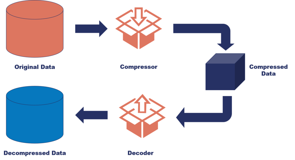
Fortunately it is not necessary to learn new protocols initially, as the data can be compressed.
For instance, using a zip format or just sending the data as a binary, would reduce the amount of data to a tenth of the size. This is fundamentally a software issue, which gives the opportunity to make power improvements long after the hardware design is complete.
Minimizing the receiver on time; that’s really down to the amount of data you want to transmit and what you’re actually communicating with.
If the system needs to be on constantly, then the receiver on time can be minimized because you already know that the system is on and can transmit at any time.
To receive from a system, you really need to know when the data is going to be sent or some way of prompting the system to send you the data. When the receiver wakes up, it can send a packet of data to the central system. The system then knows the receiver is awake and sends an immediate response.
Upon receiving that response, the receiver can then return to sleep again. That’s one way of minimizing receiver power.
There is a further step you can take. If you know there will be a response delay between your transmission and the reply, put your receiver into standby for a few ms, so it wakes just within the minimum response time. This time accounts for a tiny amount of power, but when the receiver is regularly booting, this can accumulate to hours of extra battery life.
Updating Radio Systems
There are two ways to update your radio system:
- Manually
- Over the air (OTA)
Manual Update: This involves going into each unit & updating them
OTA Update: This is where the radio itself updates the code within the unit
Clearly, OTA updates are much more efficient, however there’s a much greater chance of something going wrong. Fail safes are therefore imperative to ensure that the system will continue to work. This either be:
- The device can immediately update again
- Will store the current image and can continue to use it until the update is complete
- Use a bootloader to restart the code if it fails to receive data and request the update again. This last one has the potential to lead to security problems, which is a multi-layered issue as adding security measures uses power.
IoT security is a subject ever present in the media. There are a number of schemes used to secure data on radio links. Be aware that some have more overhead than others and either increase your CPU power and can also increase your transmitter on-time and receiver on-time because the data packets become more verbose.
Finally, Don’t Skimp on Batch Testing
With low power devices that are battery operated, you can be operating close to limits of component performance. With active devices such as FETs where you rely on a low voltage drop, for example, there will always be a variation in the characteristics between devices which may affect the performance.
It is worthwhile doing batch testing with a good-sized batch to ensure any variation will not compromise operation of the device. In addition, simulation of some simpler aspects of the design using a SPICE simulator, running tests across temperature and voltage extremes can similarly save pain in mass production.
Take the reading offline
Download the eBook: ‘Low Power Wireless Design: Saving Power in Radio Systems’ and have all the information here available, wherever you are.


Dunstan is a chartered electronics engineer who has been providing embedded systems design, production and consultancy to businesses around the world for over 30 years.
Dunstan graduated from Cambridge University with a degree in electronics engineering in 1992. After working in the industry for several years, he co-founded multi-award-winning electronics engineering consultancy ByteSnap Design in 2008. He then went on to launch international EV charging design consultancy Versinetic during the 2020 global lockdown.
An experienced conference speaker domestically and internationally, Dunstan covers several areas of electronics product development, including IoT, integrated software design and complex project management.
In his spare time, Dunstan enjoys hiking and astronomy.