OrCAD Tips & Tricks: How to Fix Partitioned Symbol Pins
OrCAD Tips and Tricks – Partitioned Symbols
(OrCAD Partitioning Gotcha!)
After a number of years without any trouble, we’ve had several instances recently of OrCAD getting partitioned symbol pins the wrong way around.
The Problem
Examples include:
- Inverters with input and output the wrong way round
- Op-Amp with + and – inputs swapped
OrCAD is getting this wrong – even though the symbol is apparently drawn correctly.
This is visible in the schematic, but easy to miss if you’re convinced the symbol is right, or if, say, one quad op-amp is right and another of the same type is wrong!
It also resists attempts to fix it – if you erase and instantiate the symbol it will look right to start with, but you’ll come back later and find it’s wrong again!
This can happen in hierarchical designs, particularly where a chip is shared among more than one block.
So, what’s the solution?
Here’s the fix…
If in the symbol editor you use the menu View>Package and THEN Edit>Properties, you get this table.
Note the Order column. All the – inputs are 0, all the + inputs are 1 etc. This is how it should be.
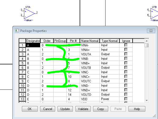
If some of the gates had item 0 = + and item 1 = – then OrCAD may swap them.
The table order seems to be determined entirely by the order in which the pins were created.
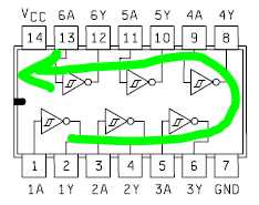
For instance, if you capture a hex inverter as pins 1-14 in ascending order:
- one side of the chip is created input-output,input-output
- while the other side is created output-inout,output-input
Presumably the solution is (in the spreadsheet entry) either:
1) List the pins in the order 1-7, 14-8 or
2) List all the inputs, then all the outputs
If you already have a symbol that has an incorrect table order, then it can be corrected like this:
1) Graphically swap the pins round by dragging them in the symbol editor (so the symbol will now look wrong)
2) Correct the pin numbers and pin names textually, so the symbol now looks as it did to start with
Hope this helps!
If you require electronic design support, a feasibility study or design rescue for your product development or contact us today on +44 121 222 5433.
How can ByteSnap help you today?
From start-ups to blue chips, ByteSnap’s electronic design engineers are enabling companies to stay a step ahead by providing them with bespoke solutions. Maintain your competitive edge – contact us today and let your business be among them!